MIPI Configuration
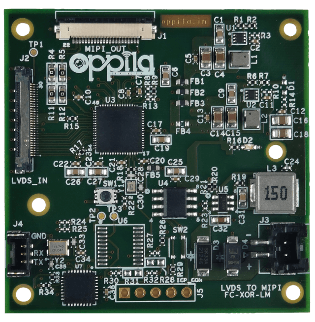
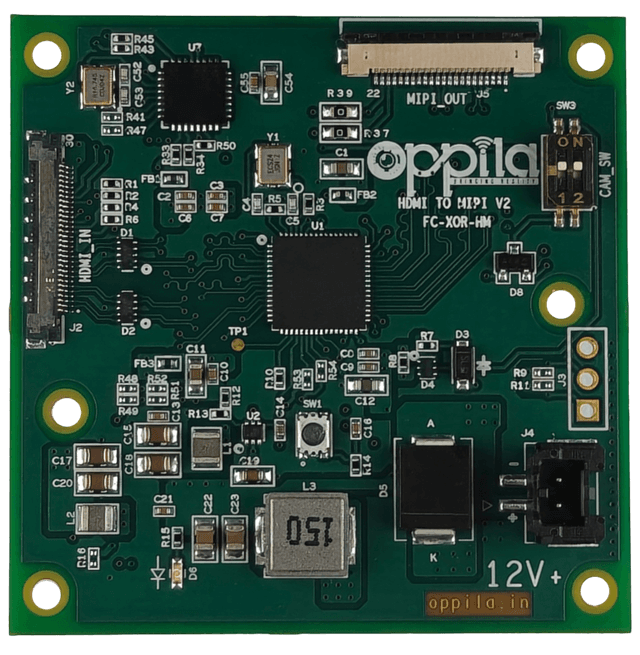
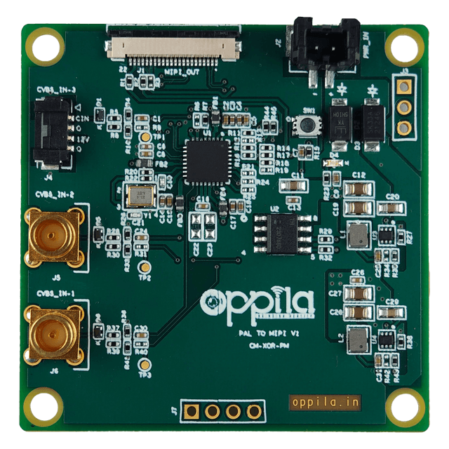
Besides the native LVDS input on J13, the AstrOptix Orin Super Carrier Board has a 22-pin MIPI CSI-2 connector (J9). You can connect an optional Oppila bridge board or MIPI camera which is having 22-pin MIPI CSI Connector to J9 to bring LVDS, HDMI, PAL or MIPI video sources into the AstrOptix Orin Super Carrier Board over MIPI CSI-2.
Each bridge board has its own driver package and configuration steps. Pick your bridge board below and follow the procedure on its documentation page.
How It Works
An LVDS camera block, HDMI source or PAL/analog camera connects to the bridge board.
The bridge board converts the incoming video to MIPI CSI-2.
The bridge board connects to J9 (top side) of the carrier board with a 22-pin MIPI CSI-2 FPC cable.
The bridge drivers and device tree overlay make the stream available as a V4L2 device for GStreamer.
Prerequisites
Before you start, make sure you have the following:
Warning
Always power off the carrier board before you connect or disconnect the bridge board on J9. Check the FPC cable orientation (contact side) at both ends before you power on.
Select Your Bridge Board