
LVDS Camera Integration with i.MX8M Plus EVK
System Block Diagram
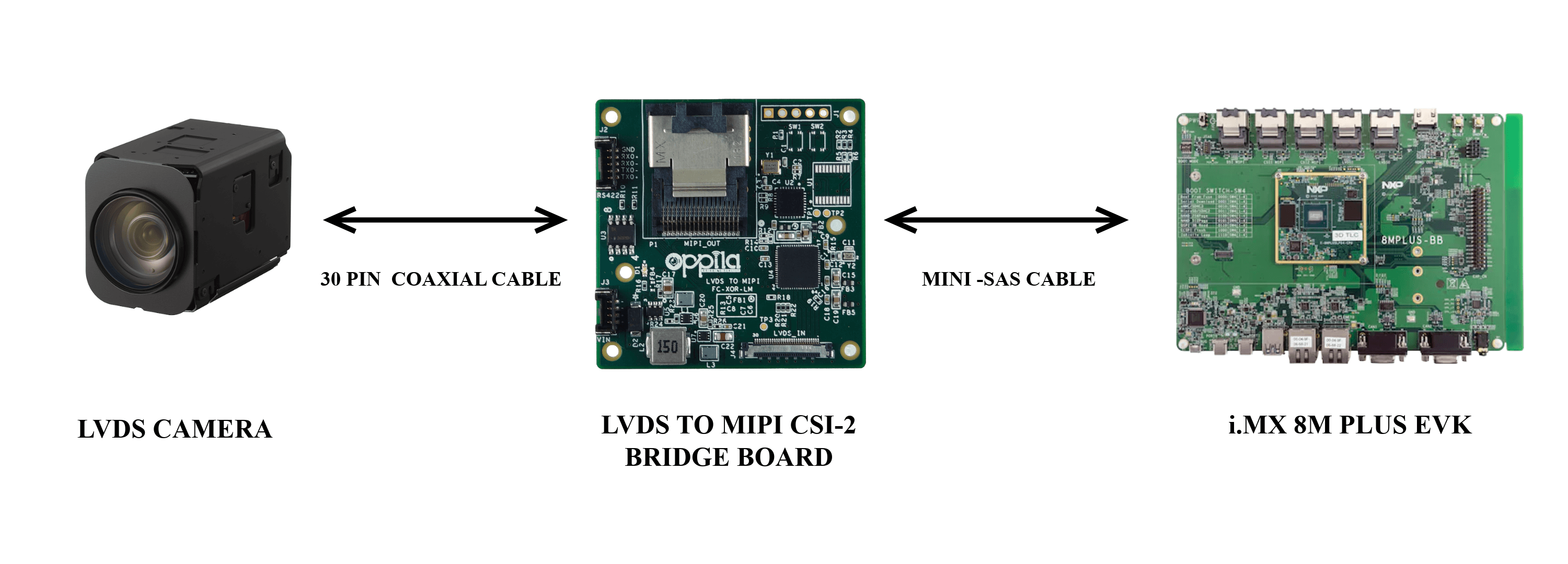
Hardware Setup
Supported Cameras
| Sony | Tamron | KT&C | Videology |
|---|---|---|---|
| FCB-EV9520L / FCB-EV9500L | MP3010M-EV | ATC-HZ5540T-LP | 24Z2.1W-10X-LVDS-462 |
Integration
1
Camera → Bridge board
Connect the LVDS camera to the bridge board via the 30-pin micro-coaxial connector.
2
Bridge board → CSI Port - i.MX8M Plus EVK
Connect the bridge board to i.MX8M Plus CSI Port using the Mini-SAS cable.
3
Power Supply
Provide a regulated 12 V DC supply to the bridge board.
Camera Control
The bridge board supports two camera control methods:
DEFAULT
Onboard I²C–UART Bridge
Camera is controlled through the onboard I²C-to-UART bridge routed to the IMX8M Plus host.
EXTERNAL
Onboard UART Header (J2)
Controls the camera from an external system via RS422.
| Designator | Functionality |
|---|---|
| R37, R41 | Presence of R37 & R41 enables I²C–UART bridge |
| R30, R32 | Presence of R30 & R32 enables RS422 control |
By default, R37 & R41 are only placed in the bridge board. To control through RS422, remove R37 & R41 and place at R30 & R32
Warning
Only one control method can be achieved at a time.