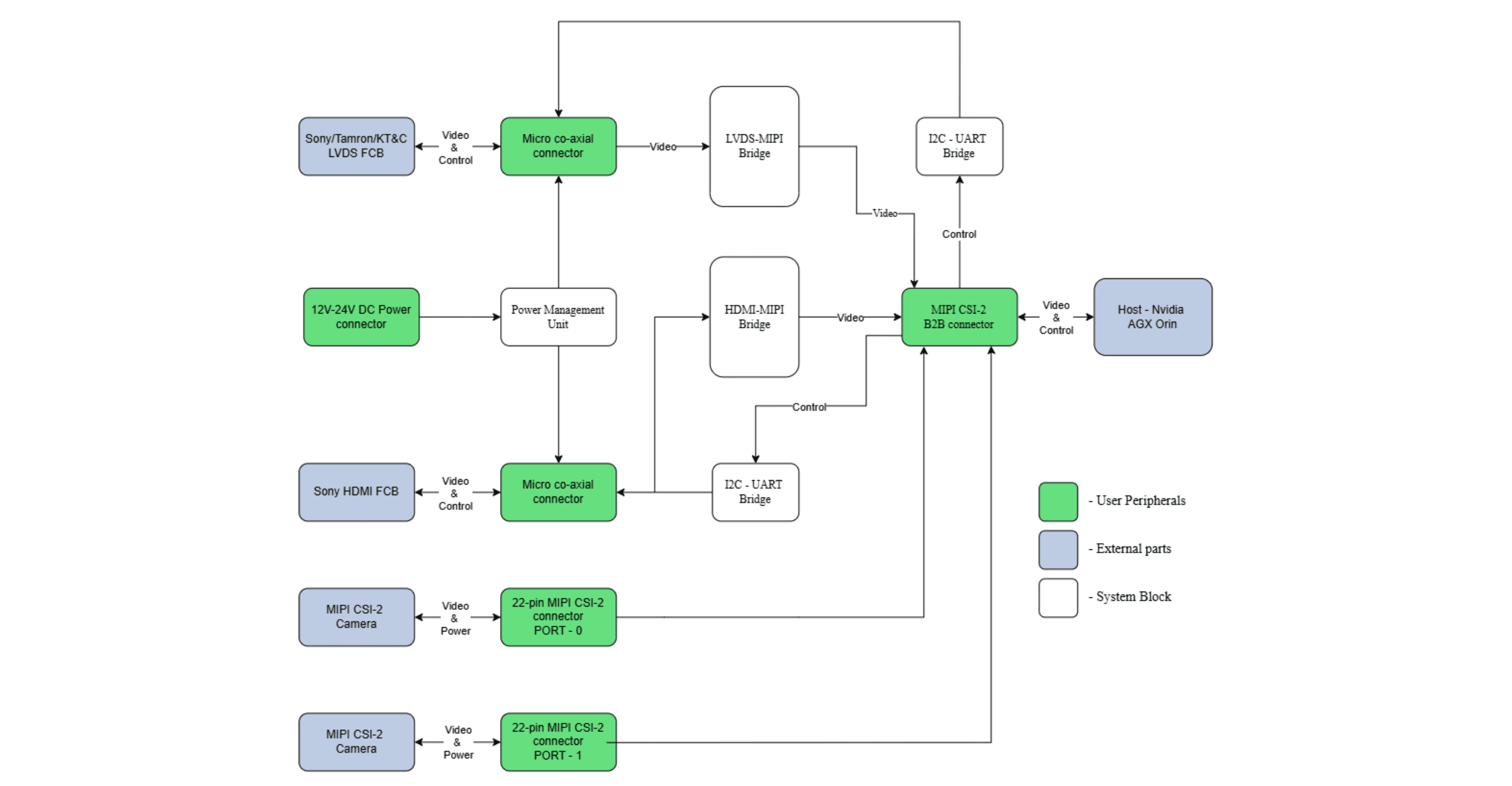
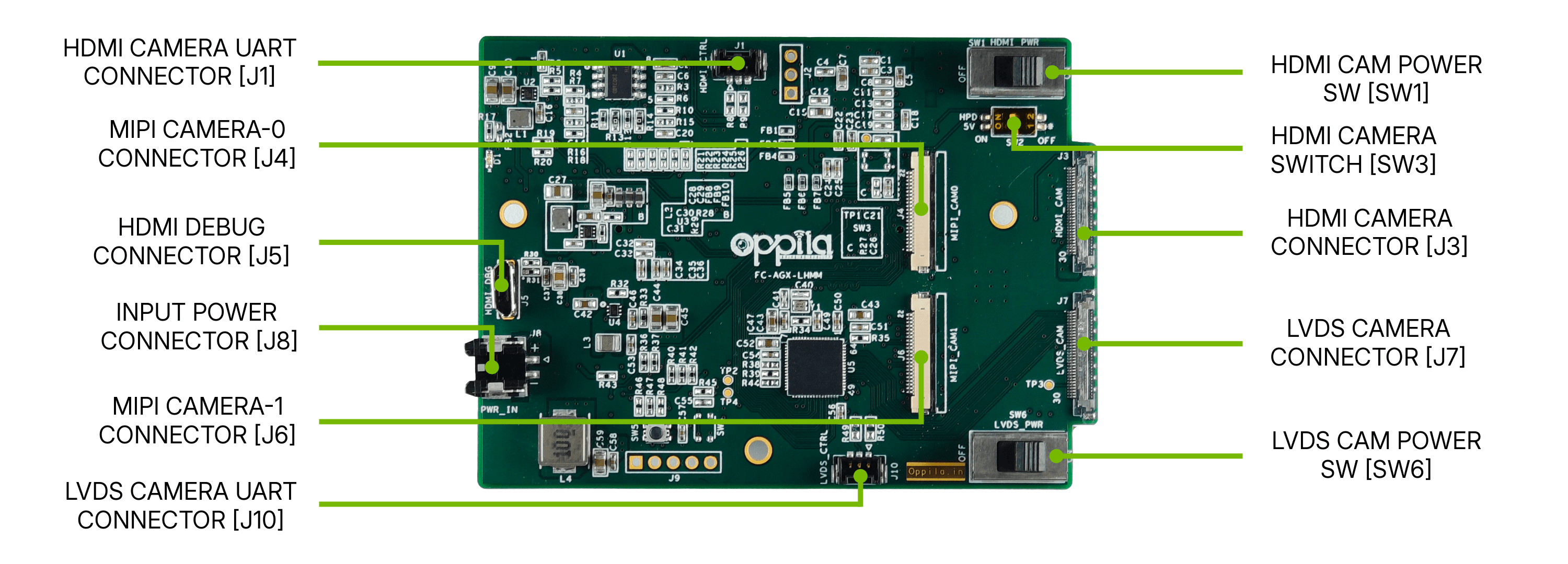
| Input Voltage | 12–24 V DC regulated, wide-input (Molex Micro-Lock Plus 2-pin connector) |
| Camera Interface | 4 independent ports: LVDS–MIPI CSI-2 (30-pin KEL, LVDS Single mode), HDMI–MIPI CSI-2 (30-pin KEL, HDMI), 2 × native MIPI CSI-2 (22-pin FPC) |
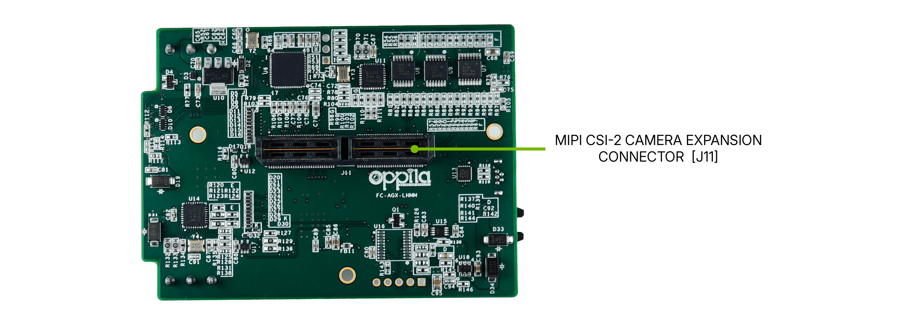
| MIPI CSI-2 Output | AGX Orin camera expansion connector compatible — 120-pin Samtec QTH-060 series, 4 × 4-lane MIPI CSI-2 |
| I²C Architecture | 3 independent I²C MUX ICs, each dedicated to a camera port group: TCA9546 for LVDS camera + control and MIPI_CAM0, TCA9543 for HDMI camera + control, another TCA9543 for MIPI_CAM1 |
| Supported Video Format | Up to 4K 60 fps (camera dependent) |
| Camera Control | VISCA over UART (3.3 V CMOS) bridged to I²C (host) for LVDS/HDMI ports, plus an external onboard UART connector for each of the LVDS and HDMI cameras |
| Indicators | Power LED (Green) |
| Board Dimensions (L × W) | 84.87 × 61.95 mm |
| Weight | 33.4 g |
| Operating Temperature | –20 °C to +85 °C |
| Compliance | MIPI CSI-2 Specification, RoHS |
| Recommended Supply | 12 V / 3 A regulated (wide-input 12–24 V tolerant) |